

Overview
| Item | Details |
|---|---|
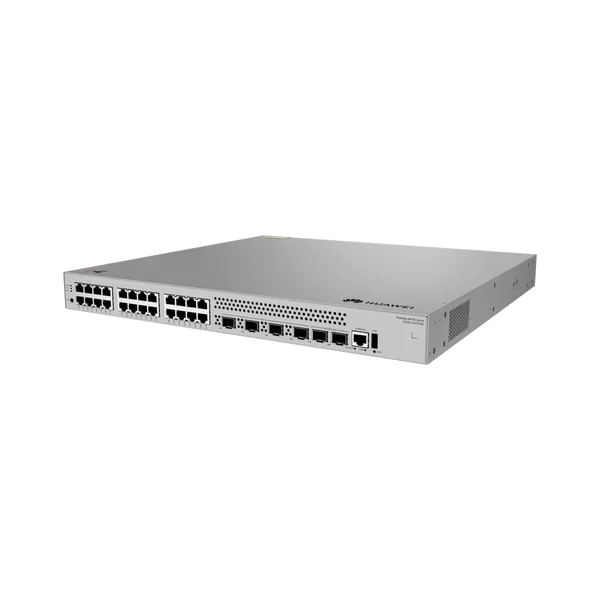
| Description | S530-24T4XE(24*10/100/1000BASE-T ports, 4*10GE SFP+ ports, 2*10GE stack ports, with 1*AC power module) |
| Part Number | 98012554 |
| Model | S530-24T4XE |
| First supported version | V600R023C10SPC600 |
Components

| 1 | One MODE button | 2 | Twenty-four 10/100/1000BASE-T ports |
| 3 | Four 10GE SFP+ ports | 4 | Two stack ports NOTE: These stack ports are available only in CLI-based O&M scenarios. |
| 5 | One console port | 6 | One USB port |
| 7 | One RST button NOTICE: To restore the factory settings and reset the device, hold down the button for at least 6 seconds. To reset the device, press the button. Resetting the device will cause service interruption. Exercise caution when you press the button. | 8 | Ground screw NOTE: It is used with a ground cable. |
| 9 | Power module slot 1 NOTE: Applicable power modules:
| 10 | Power module slot 2 NOTE: Applicable power modules:
|
Ports
| Port | Connector Type | Description | Available Components |
|---|---|---|---|
| 10/100/1000BASE-T port | RJ45 | A 10/100/1000BASE-T Ethernet electrical port sends and receives service data at 10/100/1000 Mbit/s. | Ethernet cable |
| 10GE SFP+ optical port | SFP+ | A 10GE SFP+ Ethernet optical port supports auto-sensing to 1000 Mbit/s. It sends and receives service data at 1000 Mbit/s or 10 Gbit/s. |
|
| Stack port | SFP+ | A stack port connects multiple switches through stack cables to virtualize them into one switch logically. It is used only in stacking scenarios and does not need to be configured. These stack ports are available only in CLI-based O&M scenarios. | |
| Console port | RJ45 | The console port is connected to a console for on-site configuration. | Console cable |
| USB port | USB 2.0 Type A | The USB port can have a USB flash drive connected to upgrade the switch, or transfer configuration files or other files. The USB port can only connect to a USB flash drive that complies with USB 2.0. USB flash drives from different vendors differ in model compatibility and drivers. If a USB flash drive cannot be used, try to replace it with another one from a mainstream vendor. | USB flash drive |
Indicators and Buttons

| No. | Indicator | Name | Color | Status | Description |
|---|---|---|---|---|---|
| 1 | PWR | Power module indicator | – | Off | The switch is powered off. |
| Green | Steady on | The power supply is normal. | |||
| Yellow | Steady on | The switch has multiple power modules installed. Any of the following situations occurs in a power module slot:
| |||
| 2 | SYS | System status indicator | – | Off | The system is not running. |
| Green | Fast blinking | The system is starting. | |||
| Green | Steady on | During the system startup preparation phase, the SYS indicator is steady green, which lasts for a maximum of 30 seconds. | |||
| Green | Slow blinking | The system is running normally. | |||
| Red | Steady on | The system does not work normally after registration, or alarms such as fan module, power module, optical module, or temperature alarms are generated. | |||
| 3 | MST | Stack indicator | – | Off |
|
| Green | Steady on | The stack mode is selected. The switch is a standby or slave switch in a stack, and the service port indicators show the stack ID of the switch. | |||
| Green | Blinking |
| |||
| 4 | MODE | Mode switch button | – | – |
If you do not press the MODE button within 45 seconds, the service port indicators restore to the default mode. NOTE: Hold down the mode switch button for 6s and release it to start the web initial login mode. Either of the following situations will occur:
|
| 5 | – | Service port indicator (one indicator for each port) | Arrowheads show the positions of ports. A down arrowhead indicates a port at the bottom, and an up arrowhead indicates a port at the top. | Meanings of service port indicators vary in different modes. For details, see Table 4-171. NOTE: If a power failure occurs on a device’s PCB board, indicators of the last four GE or 10GE optical ports on the device’s front panel blink green cyclically at an interval of 1 second, with each indicator illuminating for 0.25 seconds. | |
| 6 | CLOUD | Cloud indicator NOTE: In versions earlier than V600R024C00, this indicator is reserved. | – | Off | The device is not connected to the cloud. |
| Blue | Fast blinking | The device is connecting to the cloud. | |||
| Blue | Slow blinking | The device is in the cloud management state. | |||
| 7 | USB | USB-based deployment indicator | – | Off | No USB flash drive is installed, or the indicator fails. |
| Green | Steady on | USB-based deployment succeeds. If there is no deployment configuration file, deployment will be repeatedly performed. In this case, the indicator is also steady green. | |||
| Green | Blinking | USB-based deployment is in progress. | |||
| Red | Steady on | USB-based deployment fails. | |||
| Display Mode | Color | Status | Description |
|---|---|---|---|
| Default mode | – | Off | The port is not connected or has been shut down. |
| Green | Steady on | A link has been established on the port. | |
| Green | Blinking | The port is sending or receiving data. | |
| MST stack mode | – | Off | Port indicators do not show the stack ID of the switch. |
| Green | Steady on | The switch is not the master switch in a stack. If the indicator of a port is steady on, the number of this port is the stack ID of the switch. | |
| Green | Blinking | The switch is the master switch in a stack. If the indicator of a port is blinking, the number of this port is the stack ID of the switch. |
Power Supply System
The switch can use a single power module or two power modules for 1+1 power redundancy. The power modules with fans and power modules without fans cannot be installed on the same switch.
| Power Module | Heat Dissipation | Note |
|---|---|---|
| 80 W AC power module (one delivered by default) | No fan, natural heat dissipation | 80 W AC power module, 180 W AC power module, and 240 W DC power module can be used together. |
| 180 W AC power module | No fan, natural heat dissipation | |
| 240 W DC power module (available since V600R024C00 version) | No fan, natural heat dissipation | |
| 600 W AC power module | With fans, air cooling for heat dissipation | It cannot be used together with other power modules. |
Heat Dissipation System
The switch has one built-in fan for forced air cooling. Air flows in from the left, right, and front sides, and exhausts from the rear panel.

This figure only shows the airflow direction and does not depict the actual device.
Technical Specifications
| Item | Specification |
|---|---|
| Dimensions without packaging (H x W x D) [mm(in.)] | Basic dimensions (excluding the parts protruding from the body): 43.6 mm x 442.0 mm x 420.0 mm (1.72 in. x 17.40 in. x 16.54 in.) Maximum dimensions (the depth is the distance from ports on the front panel to the parts protruding from the rear panel): 43.6 mm x 442.0 mm x 446.0 mm (1.72 in. x 17.40 in. x 17.56 in.) |
| Dimensions with packaging (H x W x D) [mm(in.)] | 185.0 mm x 650.0 mm x 550.0 mm (7.28 in. x 25.59 in. x 21.65 in.) |
| Chassis height [U] | 1 U |
| Chassis material | Metal |
| Weight without packaging [kg(lb)] | 5.4 kg (11.9 lb) |
| Weight with packaging [kg(lb)] | 7.3 kg (16.09 lb) |
| Typical power consumption [W] | 26.20 W |
| Typical heat dissipation [BTU/hour] | 89.40 BTU/hour |
| Maximum power consumption [W] |
|
| Maximum heat dissipation [BTU/hour] |
|
| Static power consumption [W] | 23.2 W |
| MTBF [years] | 168.93 years |
| Availability | > 0.99999 |
| Noise at normal temperature (acoustic power) [dB(A)] | 47 dB(A) |
| Noise at normal temperature (acoustic pressure) [dB(A)] | 35 dB(A) |
| Number of card slots | 0 |
| Number of power slots | 2 |
| Number of fans modules | 1 |
| Redundant power supply | 1+1 Power modules without fans and power modules with fans cannot be installed in the same chassis. |
| Long-term operating temperature [°C(°F)] | -5°C to +50°C (23°F to 122°F) at an altitude of 0-1800 m (0-5905.44 ft.) |
| Restriction on the operating temperature variation rate [°C(°F)] | When the altitude is 1800–5000 m (5906–16404 ft.), the highest operating temperature reduces by 1°C (1.8°F) every time the altitude increases by 220 m (722 ft.). Devices cannot start when the temperature is lower than 0°C (32°F). |
| Storage temperature [°C(°F)] | –40°C to +70°C (–40°F to +158°F) |
| Long-term operating relative humidity [RH] | 5% RH to 95% RH, non-condensing |
| Long-term operating altitude [m(ft.)] | 0–5000 m (0–16404 ft.) |
| Storage altitude [m(ft.)] | 0-5000 m (0-16404 ft.) |
| Power supply mode | Pluggable power supply |
| Rated input voltage [V] |
|
| Input voltage range [V] |
|
| Maximum input current [A] | The current specifications are related to the pluggable power module. For details, see Pluggable Power Modules. |
| Memory | 2 GB |
| Flash memory | Physical space: 1 GB |
| Console port | RJ45 |
| Eth Management port | Not supported |
| USB | Supported |
| RTC | Not supported |
| RPS input | Not supported |
| Service port surge protection [kV] | Common mode: ±7 kV |
| Power supply surge protection [kV] |
|
| Ingress protection level (dustproof/waterproof) | IP20 |
| Types of fans | Built-in |
| Heat dissipation mode | Air cooling for heat dissipation, intelligent fan speed adjustment |
| Airflow direction | Air intake from left, front, and right and air exhaust from rear |
| PoE | Not supported |
| Certification | EMC certification Safety certification Manufacturing certification |
Reviews
There are no reviews yet.